HOME | DD
 bartpaaddiator — Field type superheaters
#design #engine #locomotive #steam #thermodynamics
Published: 2016-02-18 22:32:03 +0000 UTC; Views: 836; Favourites: 7; Downloads: 1
Redirect to original
Description
A steam locomotive is a power plant like any other, and it is imperative that the same design principles shall apply, with a note of the fact that the space on a locomotive is more constrained. For that reason, for example, condensing might be impractical. Nonetheless, a locomotive needs to be looked at from a view point of thermodynamics and heat transfer.The analysis of power plants always shows that the energy losses are the largest in engines and turbines. This would lead one to try and minimize the inefficiencies of the engine as a priority, however it would be a grossly erroneous course of action. For a more careful look reveals, that the losses in engines are largely ones unavoidable from not just a practical but a theoretical standpoint. This is due to the second law of thermodynamics, which implies that a heat engine, as a very theoretical construct needs to work between two reservoirs of heat, and hot one an a cold one. The heat flows from the hot to the cold reservoirs and work is being done. The first law tells us that heat and work are equivalent, ergo heat goes in and heat plus work go out. Because of the necessity of the cold reservoir, not all of the heat can be turned into work - some, or most rather, needs to be exhausted, through an exhaust or a condenser. Furthermore the efficiency depends on the working cycle of the engine. The most ideal efficiency would be one of a 'Carnot' engine - two isothermal processes of heat absorption and expulsion and two isentropic ones to close the loop. This is not realized in practice, but can be approximated by Stirling engines amongst others. The efficiency of such cycle is simply η = Tin - Tout / Tin (in Kelvin). Even if a steam engine worked by the Carnot cycle, which it does not, the maximum efficiency at 450 degC superheat and atmospheric exhaust (100 degC) would be 48% and no more could be reached, no matter how well and cleverly designed the engine would be. This efficiency will only go up if the temperatures of the cycle are changed, by higher superheat or lower temperature exhaust - such as with a condenser - with the Tout = 40 degC, the η = 56%. Of course the steam engine does not follow such an ideal cycle - it works rather by the Rankine cycle, and in that cycle the efficiencies calculated using enthalpies from steam tables are, for the given cases η = 21% and η = 37% (evaluated at 15 bar boiler pressure). The Rankine cycle efficiencies can actually be exceeded, by making the whole working cycle of the system (not just the engine itself!) closer to a Carnot cycle in shape, for example by re-superheating and regenerative feed water heating. The Carnot cycle being extrapolated from a very fundamental physical law however cannot be cheated. As noted above - limitations exist to the amount of energy we can convert into work, even in an ideal, purely theoretical situation. This amount is called exergy. We can, in a gross simplification, say that it is the amount of work a Carnot engine could get out of the given conditions. So for example, a very cold body even though it has less energy than the surroundings can have higher exergy (provided, it is cooler than the surroundings). Generally, the greater the difference of parameters versus the ambient, the greater the exergy - this is why high superheat and a cold condenser are so vital.
If the energy losses can be evaluated, so can the exergy losses. And here is where we come back to the point made in the paragraph above. Even thought the energy losses are the greatest in the engine, they are unavoidable. The exergy losses in the engine will therefore be small. Analysis of power plants show the greatest exergy losses in boilers. There are no theoretical constraints on boilers as there are on engines - a boiler can have a 100% efficiency. A Junkers calorimeter is an example of such a boiler.
Those matters were rarely considered by locomotive engineers. When efficiency would even be their concern, they would often look towards the mechanical inefficiencies of the engines. The improvements in that field were no doubt beneficial, yet the overall effect of improvements such as roller bearings was negligible - after all what could it do? Raise the mechanical (not thermal) efficiency of the drive train from 92 to 96%? Many people involved in steam engines from a hobby perspective now also often see only the mechanical inefficiencies, perhaps not realizing that they are much lesser than they assume.
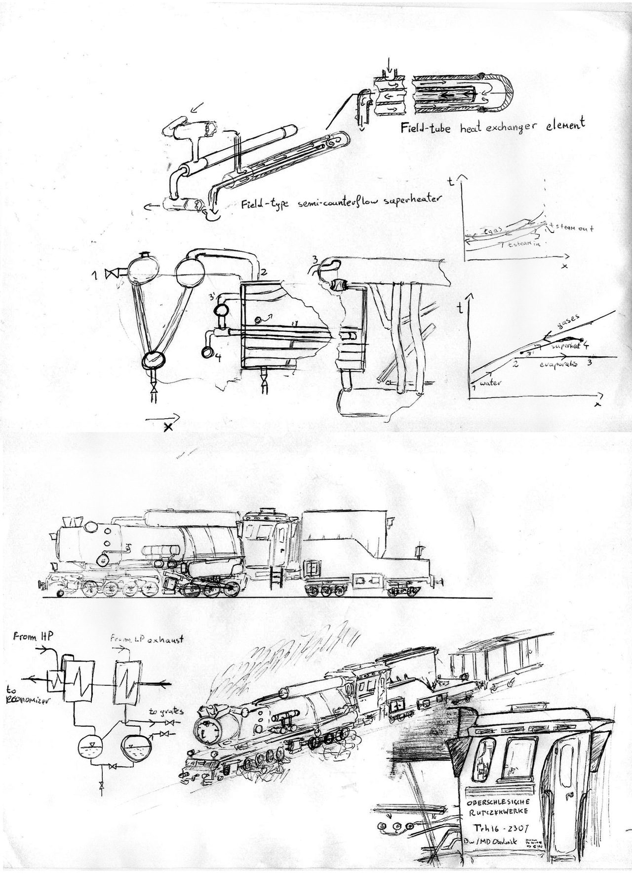
Locomotive boilers however show horrible inefficiency. In part, due to being fired more intensely than stationary boilers, the combustion is inefficient. There is also however the issue of chimney loss, not just by the incomplete combustion, but by high exhaust temperature. Locomotive boilers rarely utilized any economisers. If pre-heaters were employed, they would often rather be of the exhaust steam heated type - beneficial, as it brings the cycle closer to in shape to a Carnot cycle, nonetheless of no bearing on the chimney losses. Another problem is with superheaters. Superheaters are no more than heat exchangers, and heat exchangers are the most efficient at the counterflow arrangement (opposite flow direction), as it implies, that in a good situation the hot fluid at the outlet can have a temperature closer to the one of the cold fluid at inlet - which means, that in a boiler working at 15 bar, the gases getting out of the boiler could be cooled to 198 degC. This is not done however, due to ergonomic issues - locomotive superheaters are of a return-tube shape. This implies that if the superheater is too long it might actually heat up the exhaust gasses when the superheated steam is returning (cooling the steam!). Some were content with that as a price for increasing the superheat temperature, some were content with lower superheats, both approaches creating different kind of inefficiencies. Of course, one might think this is unavoidable - after all, if a superheater on a locomotive were to be counter-flow, the outlet would have to be somewhere in the mid boiler or firebox, and that is just a practical impossibility. It is however possible to approximate the properties of a counter-flow heat exchanger element with what is called a Field tube (named after one mr Field, not to be confused with fields of any kind). Those are used amongst other things in geothermal energy. In a counterflow Field tube superheater, the steam would go 'in' on the outside, and go out through the inside tube - if it would loose any heat, it will only be to the incoming steam, not to the stack. As the inside tube has equal pressure at both sides it can also be made of thermal isolating materials such as ceramics to minimize that. The Field tube has the additional advantage of freer expansion, and therefore the ability to withstand higher temperatures. Using Field tube superheater elements would allow therefore for a higher superheat, with a lower exhaust gases temperature (an idiom about a cake comes to mind). A Field type superheater element is shown in the drawings above.
A further increase of boiler efficiencies would need to come from the use of an economizer, an example is also shown above. Even further gains obviously can be made by feeding the economizer, much like one of a powerplant boiler, by water heated by regenerative heaters - which would 'Carnotize' the overall cycle. A locomotive utilizing all the aforementioned ideas is shown in the drawings. In it, steam from the exhaust feeds the first stage regenerative heater, and steam bled from HP cylinders the second stage. This condensate could be mixed with the feed or used for auxiliary purposes aiding the efficiency of combustion. Between them, and the economizer in the smokebox, one could also place a de-areator, to which exhaust steam from the pumps would be supplied to heat up the feed to de-areate it. Of course, in such arrangement, one would need two sets of pumps, one low pressure, pushing water from the tender, by the regenerative heaters into the de-arator (running at pressure just above atmospheric), perhaps a centrifugal pump driven by a small turbine, and a second, high pressure one, feeding the de-areated feed into the economizer, perhaps a Worthington duplex or other similar displacement pump.
Related content


Comments: 6

👍: 0 ⏩: 0

By the way I love the wheel arrangement, cab and cab script on this one, it is so unmistakably you.
👍: 0 ⏩: 0
I am so sorry I did not comment properly on these before. I see conversations about a turbo-recompressor below, and this I feel very much is pulling one's self up by the boostraps in a non condensing machine, especially something as tiny as a locomotive. The kordinas Stumpf and Porta proposed are far better
I am so thrilled to see your field superheaters (of long interest to you) and economisers (of LONG interest to me) being used, I think not incorporating something as simple as economisers on a locomotive is paramount to thermodynamic crime, even on a 3.5 inch gauge model one notices quite a performance difference with an economiser, even more than one notices with a superheater.
If I may suggest a "live" economiser, configured as such to bring the water to boiling point before entering the boiler check valve and in essence creating a semi-flash boiler power plant. THis also brings the temperature differential between ingoing feedwater and boiler water down to basically zero and relieves a lot of stress from boiler metals.
👍: 0 ⏩: 0


They are small indeed. One of the reasons is of course that higher rotational speeds decrease the wall losses in cylinders. Also for ergonomic reasons, with the large firebox of a watertube variety.
The turbo-recompressor is a viable device if condensing is to be utilized, but one has to understand that a locomotive is actually a very small powerplant - and turbomachinery at small sizes shows small internal efficiencies. Stumpf proposed devices utilizing nozzles so that the steam escaping one cylinder can reduce the backpressure on the other one by its kinetic energy, and due to simplicity it seems more viable.
👍: 0 ⏩: 0

I had to take a few minutes and read your description a couple of times. Your first few paragraphs go way over my head sir, but i understand the function and reasoning behind this field superheater. Your understanding of thermodynamics is brilliant, and is something need to keep learning about and researching to further understand it better myself. Perhaps you could tell me a bit more about the drawing to the left of the bottom most picture of the locomotive, i dont think i fully grasp the concept.
👍: 0 ⏩: 1
The first few paragraphs can be summarized as: "An engine is a box, into which heat goes in, work + waste heat come out, you cannot have an engine without the waste heat coming out, without the waste it will not work at all. Temperature is the main parameter, not anything else". Which in turn is actually the second law of thermodynamics. I thank you for the compliment, I will admit that I consider myself to somewhat understand the subject, although I will also have to say, that the paragraphs are not the difficult bits so to speak. I want to discuss those matters with you sometime again.
Left bottom - that is the regenerative pre-heater. Not related to the superheater or the economizer per-se. This is just a schematic drawing of something like an Elesco - lighting shapes are generally how one draws heat exchanger on simplified schematics. The black line of the lighting shape is the water, the box is where the steam from the exhaust and from the bleed goes and heats up the water. As the steam heats up the water it condenses a bit, and the drums at the bottom are where the steam/condensate mix goes, and can separate.
👍: 0 ⏩: 0