HOME | DD
 Hoborginc — Modular Paper AR15 V3

Published: 2011-07-25 23:28:01 +0000 UTC; Views: 213194; Favourites: 544; Downloads: 8066
Redirect to original
Description
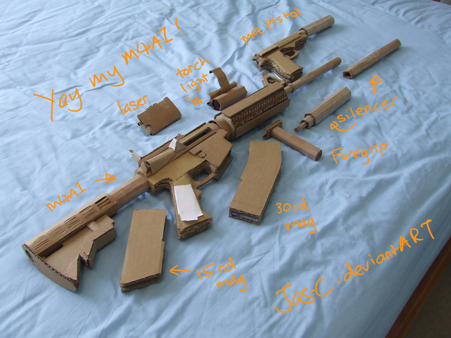
This is an AR-15 papercraft, the third iteration of a long project that has undergone several stages.AR V3A31 M4 Carbine (PNG, 70 MB) Alternative link (Mediafire)
AR V3A31 M4 Carbine (PDF, 31 MB) Alternative link (Mediafire)
Most recent version, includes basic M4 components in multiple colors. Main Page.
AR Accessories (PNG, 62 MB) Alternative link (Mediafire)
AR Accessories (PDF, 31 MB) Alternative link (Mediafire)
Compilation of accessories and parts compatible with this version.
AR V3A416 (Hk416)
Related model, with some degree of compatibility.
FAQs:
1. What kind of paper does this use?
90lbs/185g
Letter or A4 size. Scale to printable area (don't try to print them at original image size, because they won't match).
2. Where is the previous V3 package?
Superseded by the V3A31 package, which improves on it in every way. Together with the accessories package, it include a large number of previous and updated parts.
3. What do the version numbers mean?
V1 & V2: Old versions, both handmade. The receivers, barrels, and magazines are unique and incompatible with anything else. Some accessories like sights can be interchanged with other versions. Handguards are also cross-compatible, because versions 1 through 3 use barrels with the same thick diameter. However, the design quality of versions 1 and 2 is very poor, so I don't recommend building them.
V3A2: Handmade V3 lower receiver that only accepts V2 (undersized) magazines.
V3: Current version, digitalized and generally better build quality, although with some notable weaknesses, such as the barrel and stock. If a receiver is labeled V3A3, that means it takes V3 magazines. However, there are some slight differences in V3 magazines, so some may fit better than others. V3 magwell has a retaining bar at the back that holds the magazine in place.
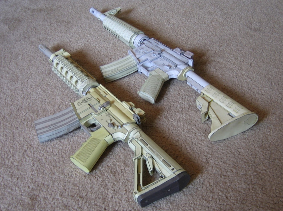
V3A416: Hk416 that uses V3 receiver measurements and magazine system. As the two-tone build shows, the receivers are cross-compatible. The main difference is the way the stock attaches (rear ring, buffer tube, and stock) and the way the barrel attaches (it goes into the upper receiver). The upper receiver also fits together better, but, being an Hk416 upper, it is taller only matches the Hk416 handguard. Overall, this is a much stronger model, but retains the unrealistic V3 magazine system.
V3A31: Same magwell and receiver dimensions, but improved buffer tube and barrel, and more realistic minor details. In short, it's an application of the lessons learned from the V3A416 model back to the standard M4 carbine configuration.
V4: Hypothetical next version, with realistic proportions and mag release. Although some of the current parts can be considered "V4" parts, I have barely started actually making a V4 receiver. The stock and barrel will attach similarly to the V3A416. There is no estimated release date.
Related content


Comments: 701

I really am impressed by these models of yours. I have downloaded them all and am just waiting to finish construction on my first one. These are wonderful models and I don't know if you hear it enough but thank you very much for all your efforts and hard work. I have really become an afficianado of these full size paper models of yours. I was wondering if I could ask you, do you think that in time, you might work in an MP-40 model or an FG-42? I have looked all over for full size replicas of these but to date, all I have been able to find are .pdo files for them which doesn't help me because I am trying to understand the workings of Pepakura and how to design models with it into paper models. If you ever getting around to doing either of them, I will definitely be snatching them up! Thanks again for all your fine work, it is appreciated. All the best to you and keep up the fine work!
👍: 0 ⏩: 1

I've taken a look at the MP-40's structure, but am not in the process of making a model of it. I haven't done anything with the FG-42 and don't intend to. There are a lot of requests that people have been making, but it's impossible for me to make everything.
There is an MP-38 and an FG-42 on only-paper.ru, but these are probably the pdo's that you've already mentioned. I don't know how buildable they actually are.
👍: 0 ⏩: 0

This AR-15 is AMAZING! I just printed it off and about to start on it, thank you Hoborginc for the design! :3
👍: 0 ⏩: 0


Can I throw airsoft parts on this bad boy or would that be bad. (Movie prop no budget)
👍: 0 ⏩: 1
Some dimensions (such as the receiver and barrel) are slightly different. You probably can't attach an airsoft handguard, for example.
Rail attachments should work, but keep in mind that even plastic airsoft parts may be too heavy to be supported by the paper (such as an AN/PEQ on a side rail). A scope on the top rail can work.
👍: 0 ⏩: 1
Alright thanks.
One more quick question. Do you know of any ways in which I could harden the paper quickly, or make it more durable. I already made your m1911 (great job) and a couple layers of clear coat stiffens it up a bit, but for an assault rifle, is there enough support for use on a run and gun film shoot? I can't do fiberglass. Any Ideas?
👍: 0 ⏩: 1
I'm not very familiar with coatings. Sorry if I can't provide much help with this subject.
But I wouldn't recommend it for a film shoot unless you actually do find a way to strengthen it.
In its regular state, you'd have to handle it in a delicate manner that wouldn't look natural.
👍: 0 ⏩: 0

Haven't made one yet but I know this will be uber cool.. been a while since i last paper-crafted something though. All the more reason to stay indoor this weekend. ^^
👍: 0 ⏩: 0

Do you happen to have a different model of the mag that isnt banana shaped?
👍: 0 ⏩: 1
There is a 20rd mag , but it's an old V2, so it's slightly smaller, and fits better in a V2 or V3A2 lower.
I can't guarantee that it stays in place on the V3A3 lower that comes with the 7-25-11 release package.
👍: 0 ⏩: 0

thank you. And really i have got some problem with printer.
👍: 0 ⏩: 0
i have a question about m4 handguard. Why side edges have different size?
👍: 0 ⏩: 1
They don't, or at least they shouldn't. If you open each page in an image editor and overlay the side edges, it becomes clear that they have the same size.
However, they might get printed as different sizes, because the page images have slightly different dimensions, so if your printer stretched the smaller pages to fit the maximum printable space of the paper, that would distort the images.
I'll fix this issue when I redo these old models with vectored versions.
👍: 0 ⏩: 0

That will make great Christmas gift if i manage to finish it in time
👍: 0 ⏩: 0

hey amazing model, but I have a question:
what parts are the ones you built in the picture? I want to build it like this except without the moveable metal sight, could you write here the parts?
Thanks
👍: 0 ⏩: 1
V3 lower - tan
V3 upper - flattop, tan
V3 grip -tan
11.5" barrel
RIS3 handguard (just one section, tan)
CTR stock - tan
Low profile flip-up sights.
👍: 0 ⏩: 1
thanks for the info!
Another small question: Since it's modular, can the sights be moved how you want?
👍: 0 ⏩: 1
All rail-mounted sights can be mounted anywhere. The barrel-mounted flip-up front sight (pictured) and the triangular front sight are attached wherever the handguard ends. All folding sights actually fold.
👍: 0 ⏩: 1
Thanks for the quick reply!
This model is just TOO awesome, when I finish a model I designed I will build it and, if you want, I'll put images on dA.
I got some more questions to be sure I can build correctly this model (I also think these questions will be useful for people that, like me, want to build this model): I use 200gsm paper for all my crafts, is it good? In what order should I build the gun? How big will the gun result if I build it like you did?
👍: 0 ⏩: 1
The scale is 1:1, so, in that configuration, it would be just over 2 feet long.
200gsm paper is fine. As long as it's thicker than printer paper, you're good.
Start with the lower receiver. It's the fundamental core of an AR and is the part that's considered a firearm on the real thing.
After that, build the grip, and then stock, upper, barrel, handguard, and everything else. Of course this is mostly at your discretion, but starting with the lower is a good idea because everything else attaches to it.
👍: 0 ⏩: 1
ok, I just started building the lower receiver but I have some questions:
Do the pivot loops glue on the right and left magwell walls?
where do the internal supports go?
Anyway this model is so easy and awesomely designed!
👍: 0 ⏩: 2
Yes, the pivot loops attach to the front of the right and left magwell walls. The walls have little flaps of the same shape to cover them up to conceal the seam.
The internal supports go inside the each magwell wall. Insert them before completely closing the magwell wall. They're just to prevent deformation. Without them, the outside face of the magwell wall might sag inward a little bit.
👍: 0 ⏩: 1
and again another question, should be the last for today, sorry to bother you: The pages look like having a layout where all the related pieces are in a single page, you made them like this or it's my imagination? If yes that means the first page has only things that go on magwell?
👍: 0 ⏩: 1
Items on a particular page are usually associated with each other, and the pages generally correspond to build sequence, but it's not always the case.
For example, the first page lets you build the two magwell walls and attach some details to them, and has no extraneous pieces. The items on the second page give you the rest of the receiver's core structure. The items on the third page can (and should) all be added after the rest of the receiver is complete.
However, this isn't always the case. On the magazine, for example, there are some boxes that go inside it, but are on the second page. On the pistol grip, for example, there are parts on page 1 that cannot be added without the parts on page 2. Sometimes, saving space on the page takes precedence over arranging them in build order.
👍: 0 ⏩: 1
another question (again): does the inner hook go inside the magwell? Should I build all the pieces before glueing them together?
the model is coming out nicely and it's intuitive
👍: 0 ⏩: 1
Build as many pieces as possible (at least on a particular page) before gluing them, mainly for your own benefit, so you can see how they fit and reduce the chance of mistakes.
The inner hook goes horizontally inside the magwell.
Just for the sake of thoroughness, I'll go into detail. See the magwell rear panel? One face has a hatched area that says "UP." This face should be oriented towards the back, and, once you get to page 3, the trigger guard will cover up this hashed area.
The face that has a hatched area resembling an "H" should be oriented towards the front, and will form part of the magwell. The vertical parts of the H are glued to the magwell right and left walls. The horizontal part of the H is where the inner hook go.
The preferred build order for page 2 is: Make the side walls, make the bottom, back, and rearmost walls, attach them to one side wall, right on the hatched parts, then put the other side wall to complete the sandwich. Take one of the magwell walls from page 1 and attach it to this sandwich, with something to hold it so it stays straight. When it's dry, add the the other wall from page 1 and the magwell front wall to complete the magwell. Only after that should you add the magwell rear wall, front lip, and inner hook. At this point the main body of the receiver is done and the rest is just details.
The purpose of the inner hook is to keep the magazine (which has a matching protrusion on its back ridge) from falling out, but still allow it to be pulled out with some force. (Obviously this isn't realistic, because including a realistic mag catch mechanism would make things more difficult to build.)
👍: 0 ⏩: 1
ok, when I asked the question I wanted to be sure because it was the last piece of the 2nd page, now I have to build the 3rdpage's pieces and I started with t he selector so I can make holes bigger if it doesn't fit without having the annoyance of the rear ring, overall the lower receiver is easier than what it looks like. You made a great papercraft. I have another question now ")
👍: 0 ⏩: 1
Yes, page 5 is always grey.
👍: 0 ⏩: 1
ok. I'm a bit confused about the rear edge part in the handle. I don't understand the part with the "grin tabs" in the txt file. Also the frontal pieces don't want to fit together for some reason, that's probably paper's thickness tho.
👍: 0 ⏩: 1
The rear edge is the curved section at the back of the grip. It has one 30 degree bend in it, hence the little cutout area. Just build it as you would build a cylinder, then bend it, applying some glue to the tabs inside that cutout area, so that they will slide under the rest of the curved section and hold it closed. It's a bit hard to describe, but just think about how you would put an angle in a cylinder.
For the front parts, keep in mind that that the order from top is: Front edge top, middle bump, front edge bottom, bottom bump. Make sure all the arrows are pointing up.
If the paper is too thick for them to fit together, it's ok for them to be 1 or 2 mm too long, but if it's noticeably wrong, pick a piece like the front edge bottom, cut the bottom off it, then push the bottom a bit farther in and glue it back on.
👍: 0 ⏩: 1
ok. i made the front pieces fit by glueing them all at one time and pushing them togther. I made the back and now I'm gonna apply the wraparound. Next is the upper receiver. This is the craft i'm building fastest so far, I love how intuitive it is.
👍: 0 ⏩: 1
Just make sure you check whether the wraparound fits before gluing it. It may need to be adjusted, or split into two.
👍: 0 ⏩: 1
The wraparound fit perfectly without the glue. I put glue and it fit almost perfectly. I'm satisfied with the result. Should I glue the handle or I can keep it as modular too?
👍: 0 ⏩: 1
Glue the grip onto the lower. There's no mechanism to keep it in place.
👍: 0 ⏩: 1
ok. I printed the upper receiver now. It looks very easy from the image instructions. My question now is: What should I do if the pins don't fit the parts?
👍: 0 ⏩: 1
If the pins are too large, you can widen the holes by making a couple of small radial cuts around them, just to make the paper around the hole more flexible.
👍: 0 ⏩: 1
oh ok. Just what I thought. Now I'm confused about the upper receiver, the instructions give a bit of help tho. I think It will be easier after I build more pieces. Some instructions look like mirrored even if they're not. I'm confused also about the ejection port. does it have some moving parts in it? I'm asking because the Ej.P Rim has written something about loops for cover axle.
👍: 0 ⏩: 1
Nothing is mirrored, it's just rotated because there's stuff going on on both sides. As long as you remember that the larger pin holes are at the front, and that the ejection port is on the right, you should be able to figure it out.
The ejection port has a pair of little loops (which are part of the "rim" component). The ejection port cover (dust cover) is a moving part, which is roughly rectangular, but has another pair of loops at the bottom. Put the cover in the ejection port (it should fit inside the rim), but don't glue it. Take the axle and stick it through both pair of loops, and then put caps on both sides of the axle so it doesn't fall out. The cover should be able to swing open, as visible on "finished01.jpg" and "finished03.jpg."
👍: 0 ⏩: 1
oh now I understand. I didn't see that there were folds on the cover and the rim, Now I understand all the model. Since the pivot pin hook looks very fragile in the hole, to make it bigger I should cut on the internal part instead of all circle, right?
👍: 0 ⏩: 1
All you need is some 1-2mm cuts around whichever circles are causing problems, whether they're on the outside or inside. It won't compromise the structure. That said, the pins should fit pretty snugly, to prevent the receiver from wobbling.
👍: 0 ⏩: 1
ok. Now I have a problem: The takedown pin hook doesn't have any holes.
P.s: Merry Christmas!
👍: 0 ⏩: 1
Wow, that was an old problem that I thought I fixed. But yeah, it seems the old pages are still in the downloadable package. Sorry about that.
Anyway, I've updated the download link.
To avoid printing out a new page, just cut them out by looking at where they are supposed to be (they're visible on the colorless version).
👍: 0 ⏩: 1
nah i can print the white version on printer paper then tape the white borders on the cardboard and track with the knife. Damn I wanted to build the model but I could build only the back of the upper receiver. Anyway thanks for the usual fast replies. Where does the Ejection port rim glue precisely? it says outside but i'm a bit confused.
👍: 0 ⏩: 1
The ejection port rim goes on the slanted portion called "Base: Right Side, Ejection Port." The rim will be the part that's externally visible. The window in it should be just a little bigger than the window directly under it, so that the cover fits snugly into place and doesn't fall through.
👍: 0 ⏩: 1
oh I get it now. Another question: does the tab on the grey inside piece glue on the left wall? It gives me extra thickness if I use it and makes the wall even harder to glue.
👍: 0 ⏩: 1
Which grey inside piece? If you mean the one on the left side of the main body shell, all its tabs attach to the main body shell.
The cutout in the left wall is just there to make some space for that protruding part of the main body shell.
👍: 0 ⏩: 1
i mean the tab in the little main body shell part, the one that shows in pg1 image
👍: 0 ⏩: 1
Oh, the bottom tab? It's there to prevent a gap from appearing at the bottom.
If attaching it to the left wall would create too much thickness, you can remove the tab and just glue the edge directly to the left wall.
👍: 0 ⏩: 1
oh ok. I removed it and I finished the walls, now I'm building the ejection port parts. Does the dust cover inner bump go on the ejection port cover, on the square of the same size? Also I noticed that there's a little part that goes inside in the main body shell. Is it for better placing?
👍: 0 ⏩: 1
<= Prev | | Next =>