HOME | DD
 PaxAeternum — Vega - The Transmitter Ship II
Published: 2017-10-23 05:07:06 +0000 UTC; Views: 1020; Favourites: 33; Downloads: 10
Redirect to original
Description
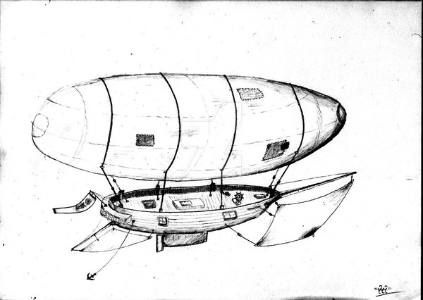
A 2200 foot airship that carries within her (or beneath her, when extended) a massive phased array curtain antenna. Seen here with the array rigged out. The antennas fold up one under the other when retracted. Regular cruising speed should be about 78 knots. She cannot exceed 15 knots with the array extended.Bands are MW 500 kHz to 1200 kHz and SW 1 to 3.2 MHz with amplitude modulation. Because the array is phased in 2 axis, she can be used for skip-propagation and at the correct altitude can be very powerful at it.
She has got a full-length keel antenna for long wave transmissions at 2 to 485 kHz. Her RF power is 2 Megawatts.
Related content


Comments: 11

Intriguing. Although, would not there be some issues involving the ship's metal air frame in regards reception/transmission? Or, for that matter, possible safety concerns involving crew when the antenna is in operation? Not sure if antennas pose the same potential hazards as high-voltage transmission lines in regards metallic objects getting rather toasty. I've never been much into electronics.
In our own modern age, I do believe the talking heads at Google or Amazon have something like this in mind. Sans massive antenna array, but such is the world we live in...
Artistically, rather minimal for a Karnes work if I do say so. Love the concept, however.
👍: 0 ⏩: 1

and I are working on actually making her frame assist the antenna, like a ground-fault resonator. It would be ideal if she had a hardwire connection to ground but because of how she operates this is not feasible.
Thankfully no hazards because she transmits in a band that is not harmful! It is the UHF range that can be very harmful, because it will literally "cook" you. Microwave, Television and up is what you need to watch out for. On the other end of the spectrum, the intense pulses of radar can also be very bad. SW can get a bit hairy but the amplitude is lower, Vega only reaches full RF power in Long wave and Medium wave which are fairly harmless bands to humans at any power level. For the sake of not only her crew but also her instruments, her gondola is plated in a way to make it RF shielded. (Not a hard thing to do as her gondola is entirely metal anyway, like a Faraday cage.)
Haha this would never serve the talking heads, this transmitter does not broadcast at nearly the high range of frequency required to carry data in its bandwidth. That kind of signal, at this power level, would definitely hurt you.
She's minimal because she's most plausible!
👍: 0 ⏩: 1

I don't see the frame proving any real issue in this case, the arrays are directional, and are targeted away from the hull. There will be some leakage, however this is not necessarily a bad thing if it is accounted for. The crew is likewise in minimal danger, as the RF is pushed away from the gondola when in normal operation. Should it be decided to use the back grid slightly out of phase with the first (a trick sometimes used to reduce transmission noise while boosting output power) it will be necessary to deactivate the screen, even in this case, however, the shape of such an antenna system will inherently travel outwards in this case perpendicular to the ship, and extend out in a balloon like shape. This leaves the gondola in an RF dead zone.
👍: 0 ⏩: 0

Not specifically, although it could be used as such. It is more intended for long range over horizon broadcasting, with a focus on acting as a flying relay station.
👍: 0 ⏩: 0

Lovely perspective and a fascinating idea.
👍: 0 ⏩: 1
and I have been concocting this one for a while now. He is still designing the tremendous power plant and transmitter to run the array, and make sure it is light enough for the thing to carry.
👍: 0 ⏩: 1
I still need to choose whether to use the semi-uniflow compound, or the vertical crankshaft engine.
👍: 0 ⏩: 1
In all honesty, because she is 2 MW RF radiative we need to make sure we can squeeze all the power out of this plant per weight and size as possible. The vertical crankshaft engine is a wonderful piece of engineering but it is rather traditional in the respect of mechanical configuration and I don't see it being as high power-to-weight as the uniflow without tearing itself completely to pieces at the RPM and steam pressure needed. I was also thinking for use on this ship the uniflow compound should be stepped up in RPM, possibly reduced in size and perhaps given an oilbath crank case.
👍: 0 ⏩: 1
Not a bad idea honestly. I could easily see this being basically a Bellis and Morcom on steroids.
👍: 0 ⏩: 1
That doesss give me some ideas......
Remember on an airship it is not just lightness but reduced or balanced reciprocating mass that is paramount, to reduce vibration. With the vertical crankshaft shared crank engine, all reciprocating masses are traveling in the same direction at any given point which would make for a huge problem. With the semi uniflow as it is currently designed this is a two crank engine with cranks at 90 so reciprocating masses are not ideally counterbalanced, especially because the uniflow piston in the LP cylinder is so large. Of course being stationary plant based your design factors this in by having the engine of large stature and bulky frame characteristics as inertial weight to absorb vibrations but such weight would crash our ship. The ideal thing is to reconfigure a uniflow engine with cranks only at 180 degree angles and the same number at 0 as there are at 180 so either a 2 crank, 4 crank engine, what have you. A 4 crank engine would considerably reduce dynamic augment. A V-configuration of cylinders applied to this design with 2 cylinders sharing each of these cranks would make for an inherently self starting engine and even torque output but it is not neccesarily required as we want this to be high RPM with a flywheel on it and once started it never really stops.
👍: 0 ⏩: 0