HOME | DD
 Widget-IV — HMS Nelson Hybrid - WIP No. 2
#3dmodel #aircraftcarrier #battleship #conceptdesign #military #navy #render #royalnavy #shipdesign #vray #warship #wwii
Published: 2020-11-20 17:40:40 +0000 UTC; Views: 1143; Favourites: 5; Downloads: 0
Redirect to original
Description
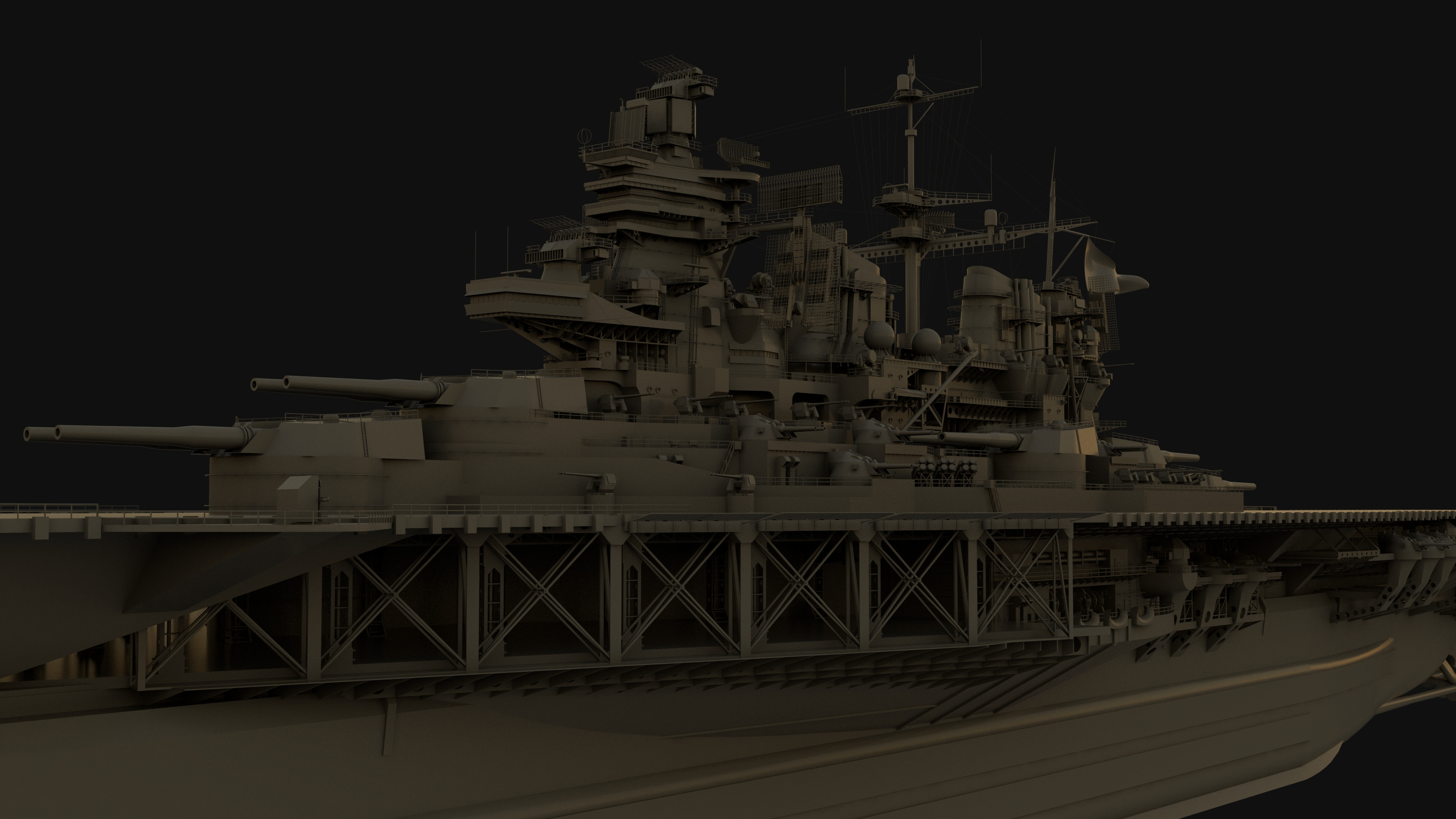
Update 2: A bit of detail work on the bridge as I build more of the fittings and structure. Also changed render settings and assigned glass and light materials. Work is slow at the moment but will hopefully speed up in January when I have a new machine.Research: I've collected hundreds of images of HMS Nelson and Rodney, as well as other British battleships. Most of them are available the Imperial War Museum. Additional photograph collections and Other information about ship fittings were found on the ontheslipway website. I've also added a few more books to my collection, mostly on British warships, Warship Construction,Shipyards, and Weapons.
IWM: www.iwm.org.uk/
ontheslipway: ontheslipway.com/
Image 1:
Overview of the ship. Only the bridge structure has detail work. There are four Bridges. From lowest to highest, they are the light conning tower, Compass/Command Bridge, Admirals Bridge, and Flying (open) Bridge. If I understand Correctly, That is one armored control station, one unarmored control station with better visibility, one command station for fleet operations without interfering with the captains vessel command, and one open station with Full visibility around the ship, save for a couple of blind spots caused by the Massive Funnels.
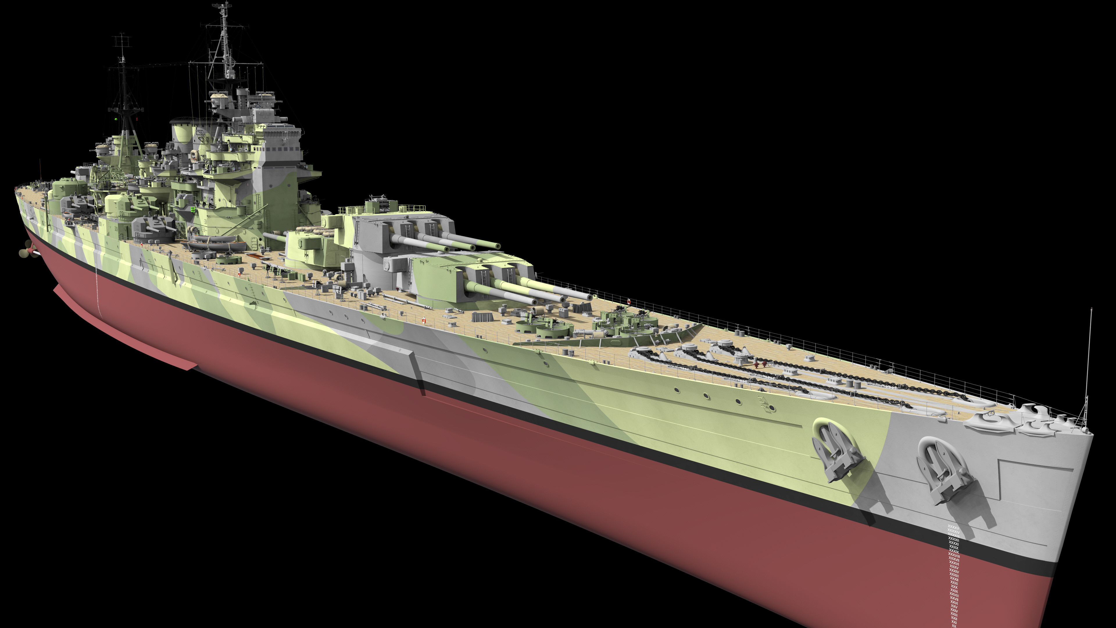
Image 2:
Added Wind Deflector, Ladders and Rail details on and around the open Bridge.
The wind deflector redirects wind upwards, creating a barrier against wind flowing above the Bulwark. I think. The open bridge isn't on the original concept drawing but I felt the space was empty and needed something. I'm not entirely sure why some of the railing details are present, but HMS Nelson and other ships had tons of them. I made an attempt to figure out where they should be based on photographs.
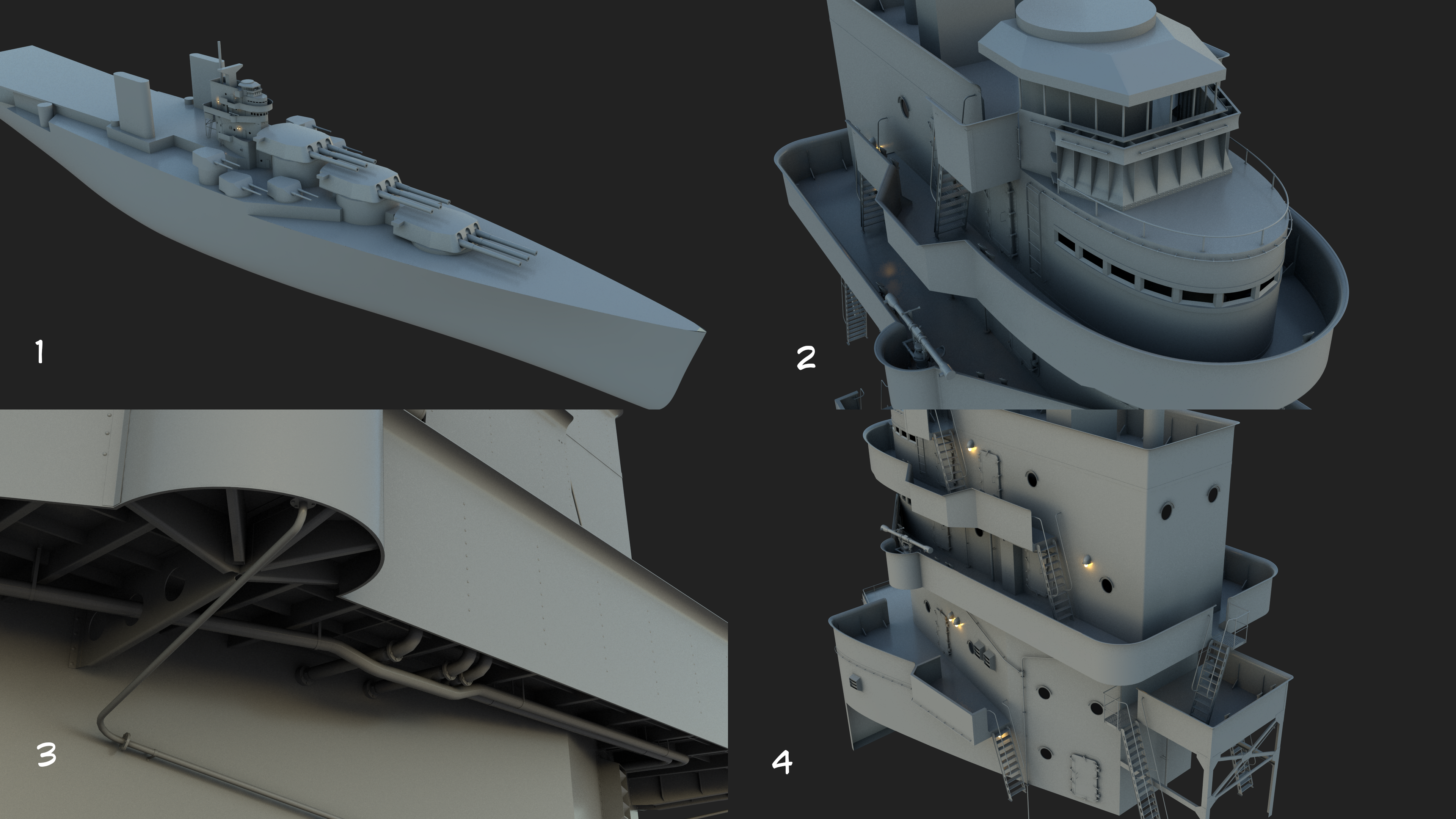
Image 3:
Added Rivets to Bulwarks and additional structural flanges for riveted construction.
I cannot show every rivet the ship would actually have, so I instead will show the more prominent ones. The bulwark rivets line up with the structural supports on the inside face of the bulwark.
Image 4:
Added an aft observation platform, Electric Lights, Lower Bulwarks and Wall Vents
The aft Platform on the bridge will overlook the aircraft elevator and Flight deck. It is equipped with multiple voice pipes to quickly relay information to the bridge about the aircraft installations. The Boiler room Downcast (intake) structure will be places in the space below the platform. Electric lights were placed in a few key places around the bridge. There aren't too many of them and some places are not lit well. The shape is my best guess based on a couple of photographs which have them. Later ships have a different shape. Vents were placed somewhat randomly along the walls. At least one of them is a Water Closet (bathroom) vent.
Next update will probably be more bridge detailing, hopefully with some of the optical bridge equipment, signal lights, COLREG sidelights, and maybe some other electrical equipment and wiring. Firefighting equipment too.
The ship is modeled in Rhino 6 and rendered with VRAY.
Feel free to leave questions, corrections/suggestions, sources for more information etc... in the comments.
Thanks, and apologies for the slowness. I hope those interested in warships will stick around for future updates.