HOME | DD
 luc1ddr3am — Compensator Prototype
Published: 2010-12-30 03:43:46 +0000 UTC; Views: 1952; Favourites: 1; Downloads: 52
Redirect to original
Description
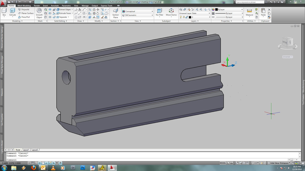
Designed to fit over the barrel of a 6" Ruger GP100. A system to secure it to the barrel/frame has not been devised as of yet. I'm playing with different ideas, but leaning towards a tension set system working with pre-existing features. I am strongly considering extending the front site tension pin into the compensator itself, and securing it with locking screw at the top of the design. (See Ruger GP100 Barrel for insight into this).Inspired by multiple designs studied over time, and the desire to add weight, and style to the stock revolver....no barrel replacement necessary. This design would make the barrel essentially square with the revolvers frame.
Pictured with variable weight underlug.
Looking for someone that has the capabilities to machine this from stainless steel and/or aluminum. Desire estimate.
Related content


Comments: 12

lol I guess I should read the comments below before asking questions
 (Smile)")
👍: 0 ⏩: 1

ahaha, sorry just got your message. You work with Solid Works?
👍: 0 ⏩: 1
I have when i was a Mechanical Engineering Major LOL
👍: 0 ⏩: 0

seams a bit love for a muzzle brake
the one on my AK-74 is a simple steal tab and the one on my Glock 35 is only about an inch out
👍: 0 ⏩: 1
Actually as pictured there is only a 1cm increase from the break from the muzzle. The design allows the heavier "slab-sided" style seen in PPC competition revolvers, and an under lug.
The prototype pictured is more of a barrel shroud than a compensator. If given the time (I have little of it) I could model the revolver into the prototype drawing to give a better idea of the function. By request I will post a 4 view, and the basic design sketches.
Essentially the internals of the block are hallowed out for the profile of the barrel's entire length. the shroud/compensator then slides over the barrel. This adds a small amount of stabilizing mass to the front of the handgun, and also provides an extra portion of steel/aluminum to drill and tap for the mounting of a customizable under lug.
👍: 0 ⏩: 1
so the gun slips in to it?
very nice and very interesting
im a sharpshooter and i am in the process of making a gun from planning to metal working to use and i love to see things like this for ideas
👍: 0 ⏩: 1
Indeed it does slide in! I've seen one Ruger revolver with this style of custom compensator/shroud. The result was actually quite attractive. I wish I could speak with the maker, but I'm probably out of luck as it was an older production.
This design is somewhat inspired by the Dan Wesson revolvers as well, in which the barrel itself is surrounded and secured to a slightly larger shroud which houses the front sight blade. These Dan Wesson revolvers still have some companies producing custom slab barrel shrouds that replace the stock shroud for competition and cosmetic use.
I need to find a machinist before I continue further. I need to know what my dimension tolerances are and what can and cannot be done cheaply. for the design to function it cannot be too loose, or too tight. Also depending on the talents of the machinist I have several mechanisms in mind for securing the attachment securely to the barrel that do not involve drilling and tapping the stock revolver barrel.
👍: 0 ⏩: 1
im not a fan of revolvers my self but i can definitely see the potential
Wesson has pumped out a series of scary looking revolvers that has been adapted in several movies
for machining it depends on a mix of your skill, location and price range
first thing that comes to mind is normally CNC milling a solid chunk of aluminum in 2 peaces and screw them togeather but normally this is really expensive
one of the easiest ways to do it is metal casting where you make your peace of of something like hard foam in 2 peaces and you place that in a type of casting sand and poor molten metal in to that sand and the metal melts the foam but leaves the sand alone creating a metal version of what you put in ... this makes a less clean post product and takes allot of sanding and a bit of milling but the process is both repeatable and cheap and has been used to make metal parts for many different things for years .. like engines, drains, bells EXC
👍: 0 ⏩: 0
AutoCAD, I've worked with solid works a little and honestly just lost the app otherwise I would have used that. AutoCAD is more second nature to me just from experience though.
👍: 0 ⏩: 1

i used solid works to make my i pod the dementions were exact
👍: 0 ⏩: 0