HOME | DD
 Taemojitsu — Guide to creating effects in MMD/MME
by
Taemojitsu — Guide to creating effects in MMD/MME
by
#mmd #mme #mikumikudance #mikumikueffect #mmeffect #hatsunemiku
Published: 2019-07-13 02:46:45 +0000 UTC; Views: 10360; Favourites: 38; Downloads: 19
Redirect to original
Description
First, how to end unemployment, fix global warming, and save the rhinos: pastebin.com/UTELVWgK
Share it with as many people as you can.
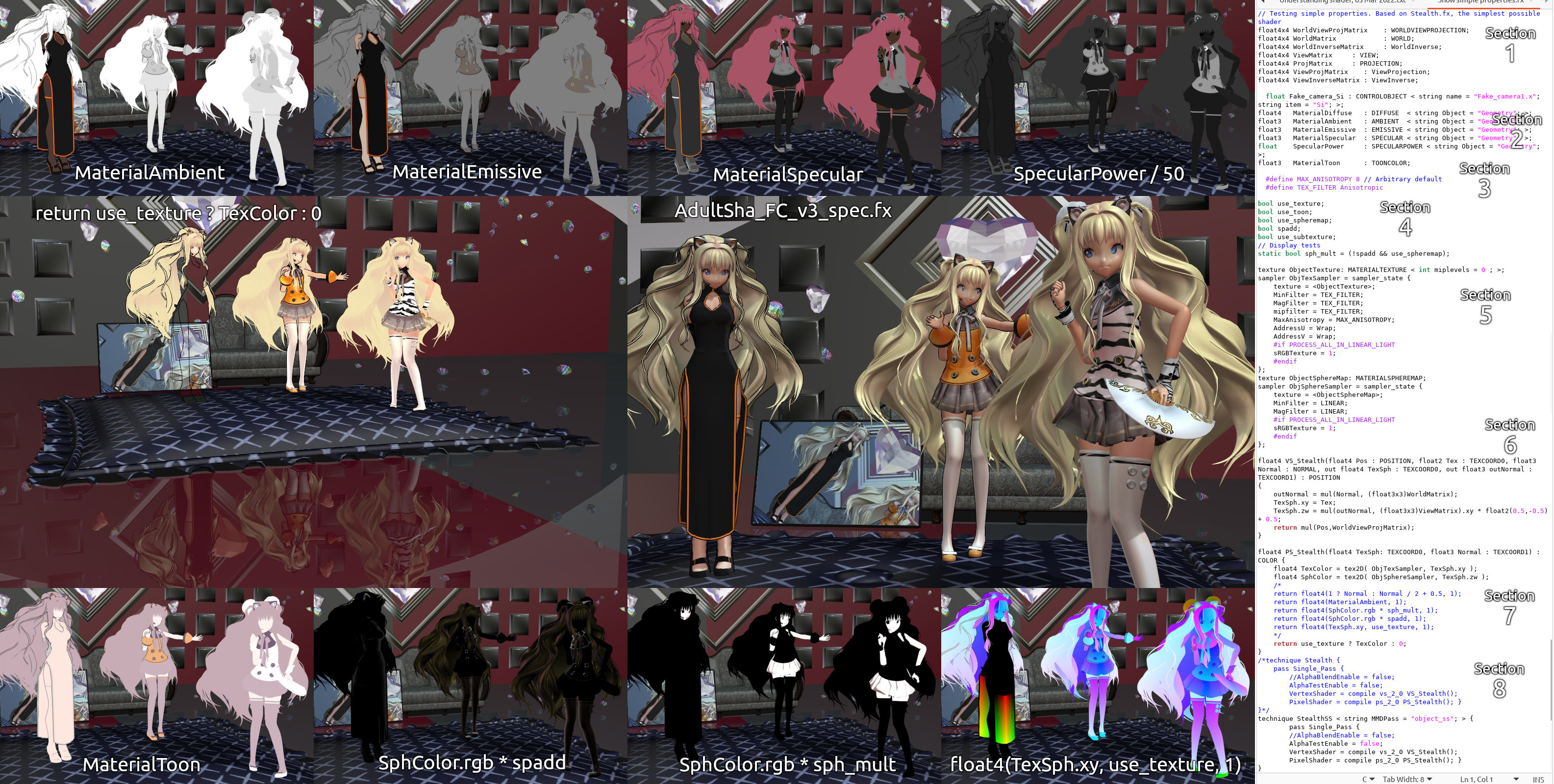
The main image, unfortunately, isn't art. I was going to do a bunch of images that showed the results as you edited an effect file. But I had to unplug my laptop's fan because it's about to break so it's really hard for me to anything in MMD.
The reference for MME, translated into English: pastebin.com/ar63p8jk
Related links, in Japanese:
sites.google.com/site/mmereference
github.com/LNSEAB/mmaccel/blob/master/test/MikuMikuDance_v926/REFERENCE.txt
sites.google.com/site/mikumikumoving/manual/effect-1
www6.atwiki.jp/vpvpwiki/pages/272.html (some effects by category, by different authors)
Getting MME to work on GNU/Linux with Wine, might work for Apple computers too: pastebin.com/c7GpQ0tm
Just as with the reference, you're welcome to translate this guide into another language and redistribute it if you find it useful.
STRUCTURE:
Background concepts
- Short explanation of gamma
- Preprocessor directives
- Confusing HLSL commands
Understanding typical effect files
Improving performance
Adding new capabilities to an effect file
___
Gamma is a way of changing how much light is added when you increase a value by 1, so that the amount of light added when the number is small is different from when the number is large. Computers use it because our eyes use it: when we look at something that's twice as bright, it looks less than twice as bright. Either the light-sensing cells in our eyes get saturated and detect less additional light, or the part of our brains that process visual input become saturated; I don't know which.
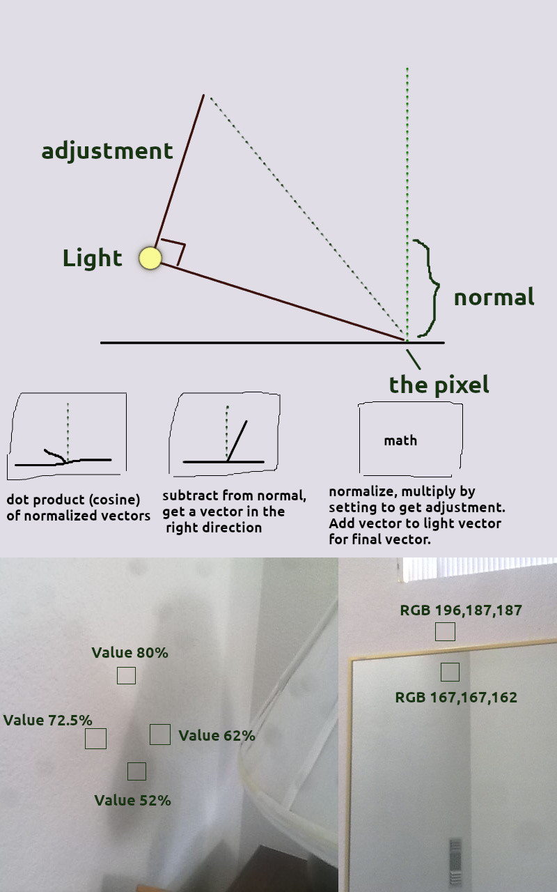
The photo of a lamp's shadow in the lower-left corner of the main image is supposed to show this. The intersection of two shadows looks slightly darker than you would expect. It's a pretty bad example, with too much ambient light and a gradient that makes comparing shadow brightness hard. If the camera, your screen, and your eyes used no gamma, then you would expect the wall with no shadow to be
Ambient + light1 + light2 = 52 + (72.5 - 52) + (62 - 52) = 82.5
A typical gamma value is 2.2. It's used in the following way; "^" means "to the power of":
(52^2.2 + (72.5^2.2 - 52^2.2) + (62^2.2 - 52^2.2))^(1/2.2) = 79.58
The actual value is 80. This is closer to the gamma value, but because of gradients and partial shadows, this is mostly a coincidence.
It's more obvious in other situations. If you have two main lights and very little background light, like two streetlamps at night, then the combined shadow will be black but a shadow from just one light will appear to be (0.5)^(1/2.2) = 0.73 times as bright as no shadow. If you have a surface like water or glass that reflects about 4% of light that approaches at a right angle, that reflection appears to be (0.04)^(1/2.2) = 0.23 of the original image, even though 96% of the light passes into the glass or water.
Gamma is important when adding light together. Default MMD does not care about gamma. If you don't do gamma, then adding a small amount of a bright light to a dark area will be too dark, and adding a weak light to a bright color will increase the color by too much.
But with most things, it's best to copy anything that was done right involving gamma rather than do it yourself. In particular, a model's spheres were created without using gamma, and since the default shader doesn't use MMD's main light to modify sphere colors, it's best not to use gamma when adding these to the main color.
If this basic introduction to gamma isn't enough, see these links:
docs.microsoft.com/en-us/windows/win32/direct3d9/gamma
developer.nvidia.com/gpugems/GPUGems3/gpugems3_ch24.html
medium.com/game-dev-daily/the-srgb-learning-curve-773b7f68cf7a
In MMD effect files, anything that starts with "//" is a comment. Anything between "/*" and "*/" is also a comment. Anything that starts with "#" is a direction for the compiler and changes the source code. These are called preprocessor directives. "#define " is used with a keyword, and whenever that keyword appears in the effect later on it's replaced with any text that follows the keyword (which can be nothing). The keyword is often capitalized to make it easier to understand. Blank keywords can be used to make it easier to enable or disable blocks of code.
The "#include " keyword substitutes text from a different file. I was going to include a bunch of examples of things you could use "#include " with to easily modify an effect, like fog, extra point lights, a satin shader, ambient light control, and simulated refraction from part of something being underwater, but these would all require testing (which I can't do because my laptop's fan is almost broken) and would delay this guide. "#include " can also be used to make different versions of an effect that you can just drop onto a model without modifying any settings or copying all the text from an effect.
Variables belong to a type. Sometimes, a value needs to be of type string, which you do by enclosing it in double quotes: "filename", but there's also a way to convert to a string using the special character "#" in a preprocessor directive.
Then if you wrote "string name = toString(TARGET_OBJECT)", it would convert the value of TARGET_OBJECT to a string.
Always edit effect files using an editor that uses syntax highlighting for source code (C or C++ source code).This will put comments in one color, preprocessor directives in another color, and many keywords in other colors, making an effect easier to understand.
More info: docs.microsoft.com/en-us/windows/win32/direct3dhlsl/dx-graphics-hlsl-appendix-preprocessor
Some keywords in MMD effect files can be hard to understand if you don't look them up.
lerp is linear interpolation, as if you put the first value at x=0, the second value at x=1, draw a line between them and extending past them, and the third value is x.
The pattern "value = expression1 ? expression2 : expression3" selects expression2 if expression1 is true (nonzero, I think), and expression3 otherwise. HLSL guide says both sides are evaluated, so this can't be used to increase speed.
Surprising or useful facts:
You can make a box that you click with the mouse using an effect. Used by seiga.nicovideo.jp/seiga/im3244207
You can store information between frames using a texture that you don't clear. Used by LimitedFrame effect. (Stores time and duplicates frames to limit fps.)
You can store information for each vertex in a texture. Motion blur effect does this.
You can use different blend modes when writing to a texture like multiplying the source and destination colors, use gamma-corrected sRGB blending even when writing to MMD's output texture, and avoid using or modifying the depth-based Z-buffer.
Can't read from any depth buffer textures, so you have to create a normal texture to use that data.
Variables with special names like "usetexture" get automaticaly modified by MME, as if by magic.
Understanding Typical Effect Files
Statements like variable declarations can be inside a function or a shader (which is really a special type of function) or outside of one. If they are outside, they are run once per material, I think. If inside a shader, they are run for every vertex (for vertex shader) or for every pixel that the vertex shader says is part of the object (for pixel shader). So in theory, by putting shared calculations outside of a shader, you can improve performance.
The vertex shader accepts data about each vertex. The exact data it cares about is defined by its arguments, but can include the vertex's 3D position in object space, the texture coordinate for a vertex for the main texture and possibly additional textures in a certain order, and maybe other things.
The vertex shader has, I think, two main purposes: move each vertex to a certain position on the output texture (also known as a render target) as well as a certain depth, which is used to determine which vertexes have priority or whether to show any of them at all, and perform calculations that have results that should vary smoothly between vertexes. An important type of calculation is texture coordinates. Supposedly, if the pixel shader needs to sample a texture at a location that wasn't calculated in the vertex shader, this texture read will be slower.
More info: stackoverflow.com/questions/20591893/why-is-a-texture-lookup-so-much-slower-than-a-direct-computation
However, if some data is just being copied from outside variables and is the same for every vertex, it should not be included in the vertex shader and passed to the pixel shader; the pixel shader should probably just access that variable itself. The default MMD shader interpolates alpha (transparency) for non-self-shadow objects like accessories, because it's copied in the vertex shader, and due to rounding errors the interpolation between 1 and 1 can be slightly less, like 0.997.
For normal objects that move about the screen as the camera does, the vertex shader transforms a vertex's position in several ways, using matrix math. First, it transforms the coordinate from object space into world space. For PMD or PMX models, this normally causes no change because things like the "All-parent bone" or the Center bone are still based on the coordinate system's origin, {0,0,0}. But this transformation might be a change if there's an "outside parent", I don't know. For accessories, this transformation does cause a change.
Then the position is transformed based on the camera, so that you can look at a model from the side or above instead of from directly in front. This is the View transformation. Finally, it's transformed so that things that should be on the same part of the output screen have the same X and Y coordinates, but different Z coordinates. This is the Projection transformation, and it also involves multiplying or dividing by the fourth number in the position, which is W; again, rather than trying to understand this it's easier to copy effects that already do what you want.
For post-effects, the position is already in the correct place, so it just gets copied.
The vertex shader will also apply a half-pixel offset to texture coordinates, so they're centered. The need to do this was removed in DirectX 10, I think, but MME is based on DirectX 9. Complicated effects that use different output texture sizes need to take care with how large a pixel is, compared to the screen.
Typical effects can do two other things here: calculate lighting for objects that don't use 'toon shading', and calculate sphere coordinates for objects that use spheres.
A lot of effects are based an effect called "full.fx", which aimed to replicate MMD's default shader. They just modify certain parts of it. In the standard model used by effects based on full.fx, Emission color differs from Ambient color in that Ambient is multiplied by MMD's main light.
With no 'toon shading', emission and ambient colors are added together. Some part of Diffuse is then added based on the orientation of that particular part of the object (the vertex's "normal", which is a line that is supposed to point directly out from the face formed by multiple vertexes), between 0 and 1. (My memory says that increasing an accessory's Diffuse could decrease brightness of the shadowed part, but the math doesn't say this and my memory could be wrong.) The resulting value is then capped at 1, which is pure white before any textures are used. So for these objects,
- Diffuse increases brightness.
- When the main light is at {0,0,0}, there's no shading from light; moving the light doesn't change anything.
- When the main light is bright, Diffuse can be 'overpowered' by Ambient and moving the light doesn't change anything.
With 'toon shading', emission and ambient colors are added together, and restricted to 1; Diffuse is ignored; and the result may be multiplied by some or all of the 'toon color' based on whether the face points toward the light. For these objects,
- 'Toon' decreases brightness.
- With the main light at {0,0,0}, 'toon' still decreases brightness and causes shading changes as the light moves.
- There's always shading changes from moving the light at maximum brightness too.
I think the way non-toon objects work is kind of broken and pretty much makes it impossible for an accessory to have the same brightness as a PMX model as you change the light intensity.
Sphere coodinates use the surface normals in the 'view space' mode but before the 'projection' transformation, and basically represent reflections of lights that don't move as the camera moves or the object rotates.
For objects that use self-shadow, whether they're accessories or PMX models, a value is also calculated that corresponds to the depth that was used to create the shadow map.
Then the position coordinates, texture coordinates, and any other information is passed to the pixel shader. For pixels that are between vertexes (all of them), values are interpolated between the vertexes that make up the face the pixel is on.
The pixel shader has several main roles. If the vertex shader output a position with a Z-value that's further from the camera than the Z-value that already exists for that pixel in the depth buffer, the pixel shader is skipped and the output image is unchanged for that pixel. You can also skip a pixel's output by calling clip() with a negative argument, though there might be some warning about "preventing early depth detection" or something. When the pixel shader does output something, it's mainly used to calculate things that don't vary linearly between vertexes and to sample textures and combine those values with other numbers.
Usually there will be more pixels than vertexes; 1280x800 = ~1 million pixels, while models in MMD typically have between a few hundred vertexes for accessories to several tens of thousands for PMX models. All floating-point values from the vertex shader need to be interpolated for each pixel, but this is probably done very efficiently.
Specific calculations often vary between the self-shadow and non-self-shadow versions of a shader. In the non-self-shadow version, the color based on light, passed by the vertex shader, is multiplied by the texture value. Then the sphere color is added after being sampled. Then 'toon' is applied. The calculation for 'toon' is not done in the vertex shader so that non-'toon' objects don't do a calculation that gets wasted, I guess.
Specular also gets calculated at some point but most objects don't use it.
For self-shadow, the color for shadows is calculated separately, called ShadowColor, which is a bit of a waste, I think. Extra calculations are also done to sample the shadow map; some effects replace this part to get better, but slower, shadows.
Typical effect files also have a bunch of defined techniques. As the reference says, an object uses only one of these techniques. Having many techniques slightly increases performance while rendering at the cost of longer compile time. The author of MME warned of 'if' statements slowing down execution and the multiple techniques guard against that.
Improving Performance
To edit effects, you need to understand what data is needed for a calculation and make sure that it's available, if the calculation is done in the pixel shader. It's easier to duplicate calculations than to identify functions that use the same variables and save that information, but this (theoretically) makes an effect slower.
I think it's common for effects to basically draw the entire scene all over again on a separate render target, copy the original screen, and combine them in a certain way. This lets a user just drag and drop an effect to integrate it into a project, without worrying about any code changes. If you understand effect files well enough to integrate different effects with each other, you can make multiple effects run more efficiently, change the settings of an effect that doesn't have a control object, and create new effects based off of your own ideas.
Could improve performance:
- moving shared calculations out of a shader
- moving calculations from pixel shader to vertex shader, including texture coordinate calculations
- avoiding texture reads inside of an 'if' statement that uses a variable that isn't a 'uniform' variable in the shader's arguments
At this point, I would start going through the sequence in the main image and copy the changes to the shader for each step. This would be like,
#include ExtraPointLights.fx
then later on, maybe split up into two parts with some of it in the vertex shader and any sampling in the pixel shader,
float3 PointLightColor1 = GetPointLightDiffuse(IN.Normal, PointLightMatrix1);
. . . or something like that. I haven't done anything with specular reflections for a point light, which I think are quite important for many materials like skin, because reflectivity greatly increases when the light is at a low angle (high angle of incidence), but the first part of the main image is the basic model for increasing the size of a point light, so the light is less concentrated. The code that accompanies it, probably finished but not turned into a function, is as follows.
#ifdef EXTRA_POINT_LIGHT_STRENGTH
(13300 characters on 115 lines omitted)
#ifdef POINT_LIGHT_MODEL3 // Put everything in one place
// Revived this! For two-sided faces, like the back of clothing or a strand of hair. Don't know why old version has POINT_LIGHT_OFFSET. Removed it and comparison with light. It didn't flip normal before; now it does.
#ifdef FLIP_BACKWARDS_NORMALS
float flipnormal = dot(NormalSaved, CameraPosition - WorldPosSaved) >= 0 ? 1 : -1;
// Just hope we don't need the non-flipped normal after this lol. (No 'NormalSavedTwice')
NormalSaved *= flipnormal;
#endif
float3 PointLightVector = PointLightOffset - IN.PosFromLight;
// This can all go in vertex shader
float3 NormalizedPointLightVector = normalize(PointLightVector);
float dotProduct1 = dot(NormalizedPointLightVector, NormalSaved);
float3 PointLightVectorShort = dotProduct1 * NormalizedPointLightVector;
float3 CorrectDirection = NormalSaved - PointLightVectorShort;
// Seemed harder to compare these. Could have done (float3 Adjustment any(abs(TrialAdjustment) > abs(MaximumAdjustment)) ? MaximumAdjustment : TrialAdjustment);
//float3 TrialAdjustment = normalize(CorrectDirection) * POINT_LIGHT_MODEL3_RADIUS;
//float3 MaximumAdjustment = CorrectDirection * length(PointLightVector) / length(PointLightVectorShort);
// The less efficient calculation
//float MaximumAdjustmentLength = length(CorrectDirection) * length(PointLightVector) / length(PointLightVectorShort);
// tan = sin/cos = sqrt(1-dotProduct1*dotProduct1)/dotProduct1, four operations?
// length is sqrt(x^2 + y^2 + z^2), 6 operations? two lengths, another divide, 13 operations total?
// Does this catch divide by zero, when light is perpendicular to normal? Result infinity, any number is less than that?
float PointLightVectorLength = length(PointLightVector); // Reused
// Testing showed need for abs() here. Math is so hard
float MaximumAdjustmentLength = PointLightVectorLength * sqrt(1 - dotProduct1 * dotProduct1) / abs(dotProduct1);
float AdjustmentLength = min(MaximumAdjustmentLength, POINT_LIGHT_MODEL3_RADIUS);
float3 AdjustedPointLightVector = PointLightVector + AdjustmentLength * normalize(CorrectDirection);
float PointLightCosine = dot(normalize(AdjustedPointLightVector), NormalSaved);
// The old version, purely for comparison (because sorting through comments to find code is hard)
/*
float SurfacePlaneLightDistance = dot(PointLightVector, NormalSaved);
float3 PlaneParallel = PointLightVector - SurfacePlaneLightDistance * NormalSaved;
float LengthOfPlaneParallel = length(PlaneParallel);
float3 PlaneParallelLimited = PlaneParallel * (LengthOfPlaneParallel == 0 ? 0 : min(POINT_LIGHT_EFFECTIVE_RADIUS, LengthOfPlaneParallel) / LengthOfPlaneParallel);
float PointLight = dot(normalize(PointLightVector - PlaneParallelLimited), NormalSaved);
*/
PointLightCosine = max((PointLightCosine + EXTRA_COSINE), 0); // Was 0.3; does somewhat similar thing except regardless of distance, so stronger at further distances. (And it doesn't fix the 'shrink to point' problem by itself.)
//float modifiedDistance = PointLightVectorLength + EXTRA_DISTANCE_FOR_POINT_LIGHT_ONLY;
// Let's try this
float modifiedDistance = PointLightVectorLength + POINT_LIGHT_MODEL3_RADIUS;
//float modifiedDistance = max(PointLightVectorLength, POINT_LIGHT_MODEL3_RADIUS * 2.0);
float PointLight = PointLightCosine / (modifiedDistance * modifiedDistance);
PointLight *= EXTRA_POINT_LIGHT_STRENGTH;
PointLight = pow(PointLight, 1/2.2);
PointLight *= AmbientColor2;
Color.rgb = max(Color.rgb,PointLight);
#endif // POINT_LIGHT_MODEL3
#endif // Point light
Edit: best version, but untested. The diagram no longer shows all the steps but it's mostly the same.
float3 PointLightVector = PointLightOffset - IN.PosFromLight;
float PointLightVectorLength = length(PointLightVector);
// Side of triangle formed by extended normal and light vector
float AdjacentLength1 = dot(PointLightVector, NormalSaved);
// Reuse name from before, has same value, except maybe with divide by zero
float dotProduct1 = AdjacentLength1 / PointLightVectorLength;
// Reused. Sine of point light vector and normal.
float sine1 = sqrt(1 - dotProduct1 * dotProduct1);
// Removed abs()
float MaximumAdjustmentLength = PointLightVectorLength * sine1 / dotProduct1;
// No restriction if below plane
float AdjustmentLength = dotProduct1 < 0 ? POINT_LIGHT_MODEL3_RADIUS : min(MaximumAdjustmentLength, POINT_LIGHT_MODEL3_RADIUS);
// Pythagorean theorem, triangle with right angle at light
float AdjustedPointLightVectorLength = sqrt(PointLightVectorLength * PointLightVectorLength + AdjustmentLength * AdjustmentLength);
// By congruence or something, adjustment vector is hypotenuse of triangle with same angle as original angle. If below plane, extra height reduces total height because of opposite sign.
float ExtraHeight = sine1 * AdjustmentLength;
// Adjacent over hypotenuse
float PointLightCosine = (AdjacentLength1 + ExtraHeight) / AdjustedPointLightVectorLength;
// 29 operations total, counting sqrt() as 1 operation, length() as 6, dot() as 5?
// For previous, counting normalize() as 9 operations, 65 operations.
In my text editor, comments (//) are blue, preprocessor directives (#) are purple, standalone numbers are pink, and 'float' is green and bolded. Makes it a lot easier to read.
The bottom-right part of the main image is a mirror. You can see that red and blue are reduced in the mirror compared to green. Changing a mirror in MMD to work the same way just requires editing the appropriate three numbers, which is easy if you understand effect files.
This is what I had planned for this guide and a previous guide:
Intro to effect editing
"Basic effect editing steps"
Task 1: Change shadow color of X-shadow for Working Floor effect. Edit defaults for ShadowColor to match ambient illumination (like a blue sky).
Task 2: Make an effect render its output at a different location so you can fade between two models without their physics interfering with each other. Add offset to vertex shader.
Task 3: add vertex-based fog to a shader, given an example of the math (or a file to use with #include ). *Enable fog only when camera is below a certain level ("water surface") (*Why fog in shader is better than post-effect that uses offscreen target for depth) Or, make fog calculate distance traveled through water! *estimate redirected light, gained and lost; either object or camera can be below water; deeper = darker. Mirror effect is extra and separate.
Transparent mirror for water surface with partially transparent objects under the water: first render mirror with ZWriteEnable = false, then render object that also samples from mirror texture with the same transparency as the water. So it writes over the water, but looks the same.
Another case: city glow at night from fog. darker when looking upwards, because less lights.
Water fog example: PK6uDRh8zN4 (that is, www.youtube.com/watch?v=PK6uDR… ) at 9:14
More realistic: variation in lighting due to surface waves and ripples that focus light. (Probably done like hologram effect's noise.)
Could have variable fog density; non-blue light is quickly absorbed in water? But travels easily in air. Fog can use lighting; 'atmospheric perspective' during the day (blue/white fog) vs in evening (red fog?)
Effects are sometimes 'wrong'. Example, specular in PanelLightObject effect.
include disadvantages: not automatically reloaded when modified; more complex = harder to find something like a function name because it's hidden in the included file, so Ctrl-F doesn't work. Harder to tell when a file will be loaded since it's not named the same as an .x or .pmx file.
Task 4: add extra lights with include, and modify diffuse (?) light strength with a function call. Could use dummy bone. (Adding extra distance from light is like a light that reflects off a curved mirror, less concentrated near its origin.) Not using plain angle between light and normal, but instead modifying it, lets you simulate a non-point source like a frosted globe.
Default shader doesn't let an object get brighter than its texture. In a bright environment, a normal camera will output somewhat saturated colors (some channels above 255 and get clipped). In order to show this some of the time, model colors are set to show it all the time. 'Toon' is a way to show correct skin colors in shadow. Default white background a possible influence.
line breaks, \r vs \n; tab width.
avoid unnecessary outputs from vertex shader, like 'DiffuseColor.a'. Interpolated and rounded down.
Task 5?: resize an object. (Dinosaur) (Not quite sure how, if you have to create a matrix or not)
Task 6: make ground shadow transparent, do color better with multiply, not update Z-buffer. (How should it interact with transparent groundshadow setting?)
Then my plans for this guide:
Guide to effect editing in MikuMikuDance
Reference manual
encourage translations into other languages (Russian, etc.) of manual and this guide
surprising:
you can make a checkbox that you click with a mouse
can store information between frames using a texture
not in manual:
can use a vertex's _index. Correction, it is in the manual
can use different blend modes, use sRGB blending, turn off Z-buffer
can't read from depth buffer, apparently
usetexture (?), other flags get automatically modified based on their name. Correction, is in the manual.
What to use as 'art' piece
Fix war, etc. Didn't intend to use DeviantArt
Dislike using images for text. Could have text as notes referenced in the image.
'Art' can show evolution of a scene.
Example of gamma: black shadow from two different lights late at night intersecting. Link to sRGB code.
1) Dolphin.
2) Dolphin in front of a television, using 'deep lens'-type effect.
3) With gamma-based (sRGB) addition.
4) With fog.
5) Dolphin looking at herself in framed mirror.
6) With accessory light that uses AutoLuminous and extra 'point' light that affects dolphin and mirror dolphin.
7) With modified mirror color calculation so edges are hazy and white, with fog in two steps.
(Point light source not yet coded, including matching directionality to the accessory. AutoLuminous object would need fog. (*underwater glow is different from being tinted; harder than just add fog.) 'Simple deep lens' with clipping, alternate texture, color controls, (...undoing blending with background,) not yet coded.)
Include project. (Blurry mirror settings, etc.)
Example 2:
1) Character riding a dinosaur that has been scaled to be smaller. Modify shader for dinosaur to shrink in size. Modify X-shadow shader for dinosaur to match shrink, and modify working floor for X-shadow to turn off reflection and match shadow color to sky illumination.
2) Add larger, glass dinosaurs around them with modified glass settings.
3) Increase scene contrast (diffuse-lighting-based or toon-based methods), use different ambient lighting than direct lighting ('toon-based' color method makes this complicated). Could try to make 'blue illumination from all sides is constant', so if main light has less blue, opposite side has more blue. Could also use gamma for angle-based fade (dot product between normal and light), which makes the illuminated side 'brighter' with delayed fade.
4) Dusk version, with different fog, different lighting, and different cubemap for glass with lerp for all.
*useful to record default/previous value when editing an effect made by someone else, especially if you're not sure what a variable does. Its creator might not record the default value separately.
Toon: front/back contrast at 0 light. Non-toon with diffuse: no contrast.
Should keep shader at each step to show changes, even if it's simple.
Another edit example: make mirrors reflect each other. Need to hardcode 'parent of parent' with a unique model name.
Difference between using accessory's XYZ and using its transformation values; outside parent
___
I think three relatively small changes that could have a large effect on how a scene looks:
1) Use ambient light controller. XYZ position controls ambient light from above, XYZ rotation controls ambient light from below. Make shadows of something in sunlight more blue, because of blue sky, or make something reflect the color of a room's wallpaper, or make the underside of a dolphin be illuminated by white sand.
2) Fog using fog controller. A single type of fog is easy; having two types of fog at different levels is harder to design and implement. For example, when underwater, water near the surface generates blue fog, but water that's deep generates black fog. In a city at night, the air generates yellow/orange fog near the surface but darker fog when looking upwards. Even one type of fog can greatly affect a scene.
3) Use 'toon' color to put more color in things as they darken, based on the theory that textures in MMD are usually desaturated due to being too bright. This depends on models that say they use 'toon' actually doing so.